Problems and Solutions
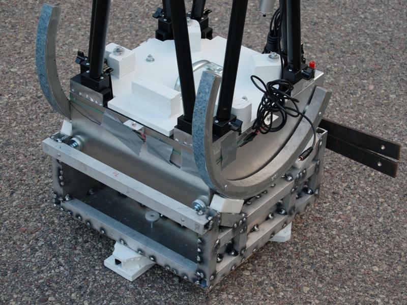
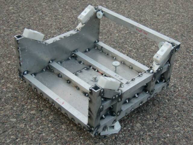
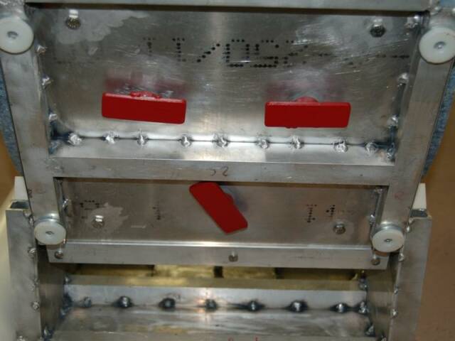
1.) Side-to-side movement of the mirror box in the rocker. I did not want the mirror box to scrape the rocker, so I needed to restrict the movement. I drilled and tapped holes in the nose on both sided for a 10-32 nylon screw. The nose of the mirror box is always somewhere inside the rocker. This wearable component is cheap and easy to replace.
2.) Lense flare from the laser pointer. I got a complaint about the laser pointer that I was using mounted on the secondary cage. It was clearly illuminating nearby objects. I figured that the offending light was diffraction right at the business end of the laser. Place a shield at that point, and all that is left is the beam into the sky. I machined a block with my CNC mini-mill out of Delrin to fit onto the laser, held fast with mylon screws. A short section of aluminum tube, blackened on the inside, went onto the opposite end. This appears to have worked, so I made two.
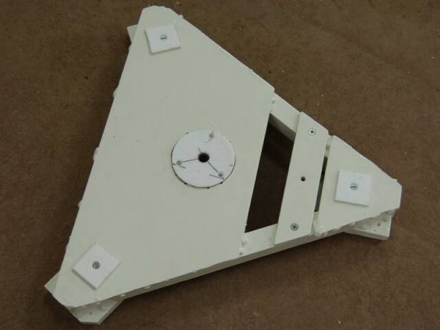
3.) Interference with the cloud detector. I had intended the cloud detector to be fixed-mounted. But it interferes with loading into my Jeep. So, I made a pivot for the detector. Two nylon screws act as stoppers for in and out position when the wing nut is tightened.
4.) Cold batteries. IDDSP 2009 was unseasonably cool, and I found out how vulnerable alkaline batteries are (not helped by an all-metal telescope). While the alkaline batteries were just temporaries until I could finish the charger for the intended NiMH batteries, I don't know how much better they would do in the cold. One idea that I have is to hybridize the battery pack. The batteries in the small box would be replaced with supercapacitors, kept charged with an external battery. This could work, were the cold-diminished batteries able to furnish enough charge, with the capacitors acting as buffer when cold.
5.) Can't adjust secondary mirror. I could not adjust the secondary mirror with a regular Allen wrench, and I had no ball-nose handy in the required size. I cut notches into the spider support to fix this problem.
6.) Difficulty adjusting primary mirror. I wanted to hand-adjust the mirror. But the mirror cell from the telescope that I scrapped for the mini-Stargate used an Allen wrench. The knurled thumb screws that I bought were just too hard to adjust. I welded steel bars to the bottoms of each, making it far easier to turn them.
7.) Focuser block. On the Stargate-3, I used wood to make the focuser block. It was easy to shape the curved hollow for the flippable filter holder. But this did not scale well for the mini-Stargate, and the focuser interfered with mounting to the secondary cage. So, I designed one out of aluminum, and the remaining wood left is that in the mirror cell.
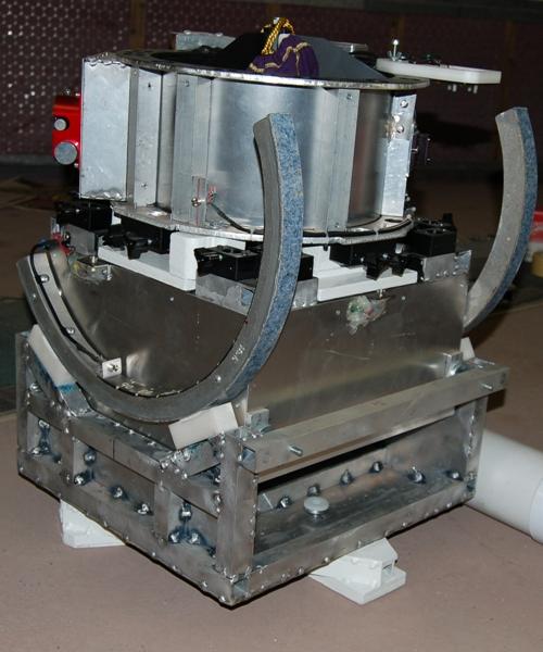
8.) Side bearing. Even though I had the rings during design, I failed to consider that the arc of the rings was less than half of a circle. So, the angle for the Delrin pads supporting the rings was off, and for months, I needed to use washers as shims to maintain proper contact. I welded in permanent shims to fix this.
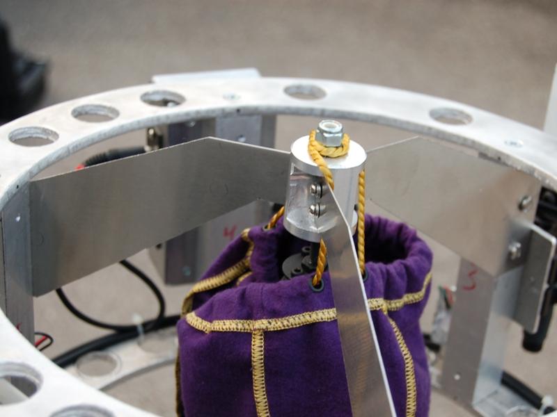
9.) Counterweight. The secondary cage is heavy enough that no one weight will keep the telescope stable at any given angle, so a variable counterweight needs to be used. It takes five plates to cover from 90 degrees to 30 degrees (13" x 2.5" x 0.25" each):
 Plate 1- 90 to 65 degrees
Plate 2- 85 to 60 degrees
Plate 3- 70 to 50 degrees
Plate 4- 65 to 40 degrees
Plate 5- 65 to 30 degrees
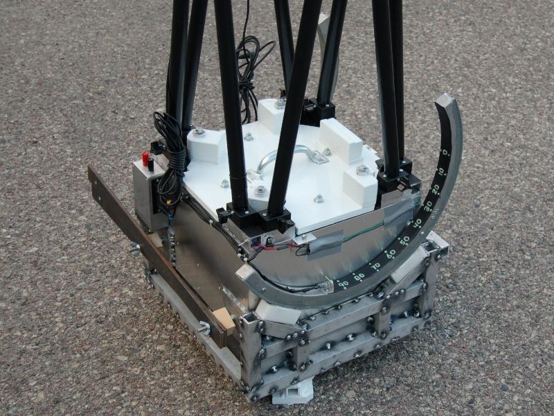
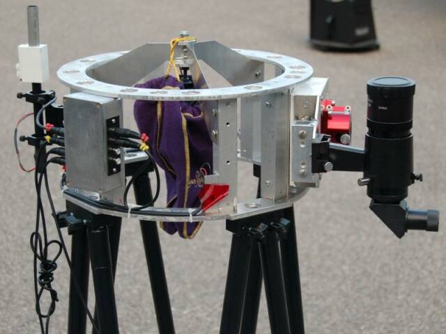
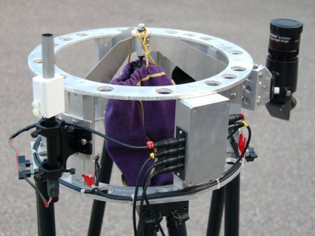
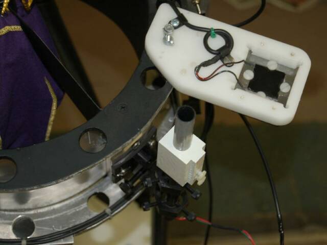
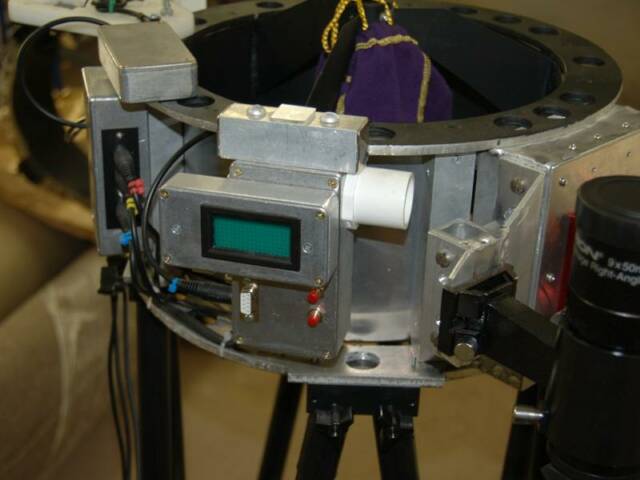
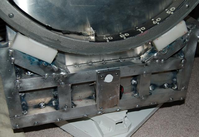
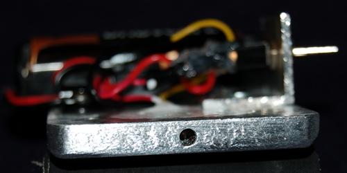
10.) Pointer for the altitude scale. On the Stargate-3, I used a pointer made from brass rod and plate; the tip was painted with the same phosphorescent paint as the numbers on the altitude scale. Turn on the UV LED, and they all glow. It worked well. Except during loading and transport. I'm surprised that I had not yet broke it. As it stands, I simply remove it now, pending a better solution. Well, I may now have one. I took a 1/4" thick piece of aluminum plate, and drilled a hole into the edge. I started with a 1/16" bit, well-lubed with WD-40 to keep it from galling, then finished with a 3mm bit (yes, I know, I mixed both English and metric). I then took a step drill, and made a 1/2" hole, approximately 3/4" from the edge. I then filed a flat spot where the 3mm hole came through. With this done, I inserted a red T1-sized (3mm) LED with a water-clear (NOT diffused) lens into the hole. This acted to restrict the view of the LED. You have to be standing straight overhead to see it. It worked well, so I drilled holes to permanently mount it to the rocker. When done, the pointer will be very resistant to abuse.
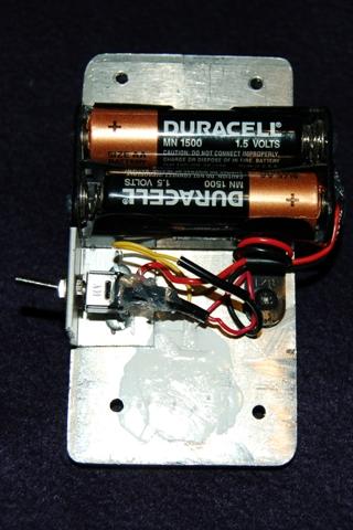
Lighting the LED had some problems. Since this pointer is mounted on the rocker, I had to furnish a power supply. My first thought was to use a solar cell to charge up a supercapacitor during the day. And this worked. At least, until I potted the hole with epoxy to keep out water. Before, the 1F capacitor I used could keep the LED lit at a suitable level for more than a day. Adding the epoxy, that dropped down to hours! I'm not quite sure at the why of this. My LCR meter could not measure the resistance of a sample of the epoxy. And I'm not sure that epoxy resistance is the cause. I was able to "short" out the LED with my fingers. Considering that I was dealing with current measured in microamps, I am not surprised. In any case, I do not have the test equipment needed to verify any of this (such as a megohmmeter). So, I had to resort to Plan 'B'. 'B' as in battery. After experimenting with the size of the biasing resistor, I mounted a battery holder and switch to the back of the plate. I admit that the whole thing looks conspicuously like a bomb. And I am still wondering if I wasted my time even including an on/off switch. Why? A red LED biased with a 3 volt battery and limited by a 470K resistor means a current of about 6 microamps. An AA-sized battery is rated around 2850mAH. Theoretically, that should keep the LED lit for over 50 years! But all batteries self-discharge, and these batteries should be stone-cold dead long before then. Possibly, me too!