The SG-NG controller is intended to monitor and control the mirror temperatures, determine position and control drive motors (if used), display time and field conditions (temperature and dew point), process science package measurements to calculate sky conditions, plus other miscellaneous functions (e.g., beacon lights). The science package will carry over sensors used on both the Stargate-3 and mini-Stargate, plus some new ones. There will be sensors to measure mirror temperature, air temperature, sky temperature, relative humidity, ambient light, barometric pressure and position.
Mirror Temperature
For measuring temperature of the primary and secondary mirrors, I will use the tried-and-true LM335AZ. This sensor generates an output in millivolts per degrees Kelvin and is easy to work with. Relative humidity will also be used to calculate dew point warnings and quantify observing condition quality.
Air Temperature & Relative Humidity
An integrated temperature / RH sensor will be used to measure air temperature and relative humidity.
Sky Temperature
The cloud detector originally used a thermoelectric cooler as a thermopile to measure sky-ground temperature. Later, I intended (on the mini-Stargate) to use it to quantify observing condition quality. A cooler sky (not air temperature) means that the atmosphere is less of an obstruction to radiating heat into space. If the sky is more or less able to radiate heat (as infrared light) out, it is also more or less able to let visible light in (and with less scattering). But the current cloud detector is only a relative temperature detector. My intention is to change it to an absolute temperature detector. The ground side temperature of the detector will be measured, and used as a reference against the output of the cloud detector to measure absolute sky temperature. Also, an idea under consideration is to use a second thermoelectric cooler against the ground side to keep it at a fixed temperature. As the output of the cloud detector is non-linear, having two variables (ground temperature and sky temperature) makes it hard to calibrate and to get accurate numbers.
Ambient Light
Ambient light level will be measured using a TSL230. Light level is converted from voltage into frequency, making it easy for the controller to measure. Also, since this metric is for visible light only, an infrared filter will be added.
Barometric Pressure
Barometric pressure will be used to quantify observing conditions. Thinner air lets more light through and scatters it less.
Position
Encoders for altitude and azimuth will be used in combination with a GPS module to determine where the telescope is pointed. Hall Effect sensors will be used to sense home and overtravel positions.
August 27, 2011
I came up with an idea (related to calculating magnitude limits) for an atmospheric haze detector. One approach employs a laser aimed at a linear sensor to measure the amount of scattering by the air. I tried both a green laser (536 nm) and blue laser (405 nm) to maximize Rayleigh scattering. But I just could not get either to appreciably scatter in such a short distance (5 feet max). Plan 'B' is to try using an absorptive spectroscopy approach. But I'm doubtful that I could make that work in the same small distance (I will try, however). Looks like water vapor will be the only atmospheric component (besides pressure) that I can measure.
Also, the concept of distributed processing is shaping up. There will be separate controllers for various functions (there is too much for one controller to deal with, not enough I/O lines); each node will connect to the other as part of an RS-485 network. Master will be on the secondary cage, while the slaves will be on the mirror box. There will be nodes for temperature control, position detection and possible motor control. I am also exploring the idea of using a 2D accelerometer chip as a tilt detector, as opposed to an optical detector. My goal is to eliminate cables runs where possible. Also, the beacons will be switched directly by the controller. I had a complaint that the flash was interfering with another observer engaged in astrophotography, and this way I can turn them on or off at will, as well as eliminate hardware.
October 8, 2011
My test of the science package at IDSSP 2011 was not a success, and forced me to reconsider the design. Since then, I have been busily researching the subject of IR thermometry. All matter above absolute zero (0 °K = -273.15 °C = -459.67 °F) emits radiation proportional to its temperature. Using Wein's displacement law gives an approximation of the peak emission wavelength:
λmax = 2898 / T
where:
λmax = wavelength of peak energy in microns (μm)
T = degrees Kelvin (°K)
My target range is from 8-14μm, or approximately -87 °F to 192 °F. And ideas have been plentiful. First, the sky temperature sensor does need the reference side to be at a fixed temperature, so a second thermoelectric cooler will be added. I will have to experiment to determine what the best temperature is. Do I make it relatively high to maximize the sky-reference temperature difference, and therefore, the output signal? Or is this approach counterproductive and I, instead, need to keep the reference cool? Another area of experimentation is to increase the detectivity (D*)- I want the sky facing side to be blacker-than-black to infrared. One thing that I will try is powdered carbon, held fast in a binder of some sort (paint, silicone rubber, epoxy, etc.). And how large does the sensor need to be? I have thermoelectric coolers ranging in size from 15mm square to 40mm square. I am also considering more exotic detectors to get better D* values than a thermopile (the thermoelectric cooler is in essense a multitude of thermocouples- a thermopile- wired electrically in series, thermally in parallel) can deliver. One candidate is mercury-cadmium-telluride (MCT or HgCdTe). Cooling it will be a limitation, though- it works best with liquid nitrogen (77 °K). Some do come with thermolectric coolers built in, though.
Next, the ambient light detector did work, but it was also problematic. First, Jim Edgars State Park (near Springfield, IL) is far from the darkest place on the planet, and I got very long pulses out of the TSL230 (perhaps 0.1 Hz). I would no longer be counting pulses, but measuring period at that low frequency. Second, I don't know what the darkest sky this device can measure is. If the values measured at JESP is the bottom, then I need a more sensitive detector. Perhaps I may need two- a dark sky and not-so-dark sky detector if the dynamic range of either is limited (either saturating or bottoming out). Two possible candidates here- a large-area photodiode (LAPD- and I just happen to have one!), and an avalanche photodiode.
Controller and Science Package
This page was last updated: March 25, 2014
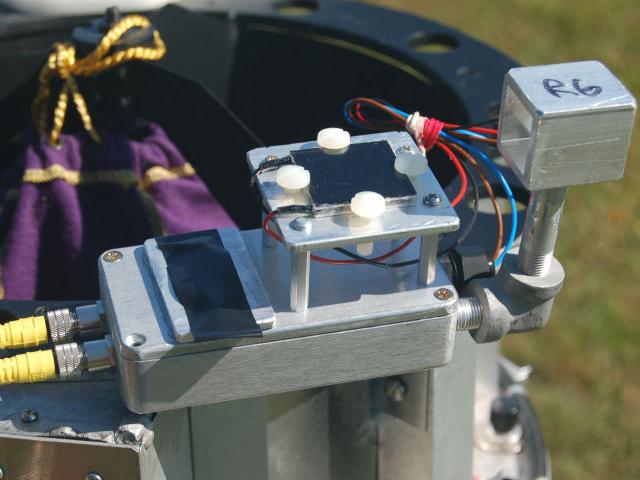
The science package (v1.0). Tape cavers the window for the ambient light detector. The sky temperature sensor is held in place with four nylon screws. Off to the far right is the air temperature sensor.
October 11, 2011
The Day After. I called yesterday to get a price on the MCT sensor that I was considering. Well, until I got the price. I didn't get all of it; my brain just stopped working after the "one thousand" part. Ok, thermopile it is. It may be to my advantage, anyways. While the MCT sensor has an order of magnitude better detectability and has a limited spectral response range, the thermopile's response range is largely flat, and is much wider. Plus, the MCT detector has an active area of 1 mm square, while the thermopile is 40 mm square. What I don't know is what the coldest is that I can expect to measure, or what the thermopile is capable of measuring. As it is, I measured a sky temperature of -53 °F with my Extech IR201 Pocket IR meter, at a relatively low altitude (in central Illinois). My IR meter is spec'd at -58 °F. In a trip coming in six weeks, sky permitting, I will get to test both my IR meter and v2.0 in a mountainous area. Also, I got good results with coating surfaces with powdered charcoal, although I will need to screen out larger grains better.
On another topic, the failure of both laser pointers at IDSSP 2011. They both worked two months ago at WOW 2011. I could understand the handheld pointer, as cold as it was. Alkaline batteries don't like the cold. But the one mounted on the mini-Stargate is powered from lithium batteries going to a DC-DC converter. The standard output was 3.3V, so I adjusted it down so as not to damage the laser. But did I have the voltage too low to begin with? And does cold affect the lasing voltage? Maybe I need some sort of temperature compensation. I rely on that pointer for aiming my telescope- I expect total reliability.
October 16, 2011
Well, I don't know yet if temperature shifts the lasing voltage for a green laser, but low temperature definitely was the cause of both pointers not working. Both work perfectly now. At room temperature. I took the modified one (with a power cord added) and chilled it down in the freezer. Absolutely dead. Until I warmed it back up. First glowing weakly, then at full brightness. I thought heat was the laser's main enemy. Am I now going to have to provide heat to keep it working in the cold?
October 17, 2011
The answer is yes. I contacted laser experimenter guru Sam Goldwasser and told him the problem. His response was basically that the cold most likely had shifted the laser diode's wavelength (perhaps 1/3 nm / °C) to the point that lasing was not possible. So, heating the laser appears to be my only option. I will experiment with both resistors and thermoelectric modules to see which heats the best with the least power- battery power.
November 2. 2011
After adding up the power consumption of the laser, laser heater and the heater for the sky sensor, I realized that I was going to have a serious energy budget. While there is not much I can do about the first two (besides not using them), I can drop the third. The thermopile for the sky sensor measures differences, not absolute values. By keeping the reference side at a fixed temperature, I can determine the skyward temperature. Or I could measure the temperature of the reference side, but that would require another A/D conversion. The fixed reference temperature version had an advantage also of maximizing the temperature differential. But it's a power hog. What's left? A cold junction compensator. A thermopile is simply a number of thermocouples in series, and like a thermocouple, has a reference side and a measurement side. Thermocouple tables are calculated using the reference being kept in an ice bath. A cold junction compensator works by sensing the temperature and adding an offset to simulate its being in an ice bath. For me, though, I have the challenge that commercially available cold junction compensators (such as the LT1025, which I favor) are designed for standard thermocouples. A thermoelectric cooler was not designed for the purpose of temperature sensing, so there are no tables for each junction. And even if there were, there are over one hundred junctions. So, I will have to set up an experiment to calculate a table of values of my own. Then, using a circuit gleaned from National Semiconductor's app note AN-225, build my own compensator.
January 8, 2012
I came up with another possible expansion of the science package- a spectrometer. I found an imaging prototype board for robotics that might be sensitive enough, since it allows integration (timed exposures). Or perhaps a single element sensor to scan with a small motor. Couple this with a diffraction grating, and voila, a poor-man's spectrometer. In any case, for sure, I will include an RS-485 port on the secondary cage for any possible future expansions.
November 3. 2012
I came up with a better idea for the telescope beacon. Originally, I used a circuit designed for those roadside highway flashers. But there was only so far I could extend the flash period without "softening" the flash too much. Plus, I had no control, should I want to disable the function. And it comprised of a dozen or so discrete components. I wanted a 5-10 second interval, and a short (100 mS) on-off pulse (so as to to catch the eye without needing to be excessively bright). I was preparing to program a small PIC-type controller to do this, but did not want to invest in the development time now. However, I stumbled onto an Ideas For Design circuit (Electronic Design, Dec 3, 2001) that did just what I wanted with a microprocessor supervisory chip. The chip in the IFD was only available in an SMT package- unfriendly to my aging eyes and shaky hands, so I had to find one in a DIP package. While my search took hours, I did find a Maxim chip that worked perfectly. Now this may seem like a lot of effort for such a seemingly trivial function. But would you want someone to bump into your telescope in the dark? You know, the one with thousands of dollars in parts and endless hours of design and construction time in it? I thought not.
December 2, 2012
It's been a week since the idea of equipping the SG-NG with sensors to detect auroras came about. But both have significant design challenges. The first, the multi-axis fluxgate magnetometer, intended to sense geomagnetic storms, needs to be far from anything metallic. I assume that to be ferrous metallic. Will it work mounted on a telescope made of aluminum and stainless steel? The second, dubbed SAM (Steve's Aurora Monitor), intended to detect light emissions from aurorae at 557.7 nm (oxygen), is challenged by questions of sensitivity. I want to use an avalanche photodiode (APD). But can it compete with a photomultiplier tube (PMT)? Both approaches are costly. The PMT approach is probably outside of my pain threshold, plus it would be bulkier than an APD-based design. I want the optical assembly (filter, PCX lense, APD) separate from the electronics. As it is, Samantha (connected to O'Neill by a dedicated RS-485 link) will require a processor to handle the science instruments. For now, I will continue with the APD design and will order parts soon to prototype a power supply / monitor for this expensive diode. I have not receive the APD datasheets from my vendor yet.
December 15, 2012
Design work on SAM has taken on a life of its own, complete with unexpected turns. First, I am exploring the practicality of a dual monitor to cover a second area of spectrum (620~670 nm [red], in addition to 557.7 nm [yellow-green]), maximizing the chance of detecting an event. Doubts about APD sensitivity grew to the point of reconsidering a PMT. While searching for design literature, I stumbled onto an alternative- a silicon photomultiplier (SPM). While touting the strengths of the PMT, it claimed the advantages of an APD. Oh, and the interface circuit sounds simpler. It sounded too good to be true. Still, if I can have the best of both worlds, I have to try one to find out.
January 28, 2013
I will order parts for the SAM shortly. In thinking about the SPM, I planned on trying first the non-TE cooled version, as the power demand for this always-on device would require hefty batteries. However, the SPM gives new life to a photospectrometer- even if it requires a TE-cooled unit- since it is only an on-demand device. As it stands, I have a rather lengthy list of sensors on the wish list, for various reasons:
RH sensor- Dewpoint warning and sky quality calculations
Ring thermocouple- Monitors ring temperature to compare with dew point
Air temperature sensor- Dewpoint calculations
Moving air sensor- sky quality calculations (proposed)
I have added more ideas to the sensor list- all mainly for radio astronomy. It all started with looking for a suitable receiver to pick up lightning strikes as a storm warning monitor. Looking for suitable VLF receiver designs led to VLF monitoring. I had, beforehand, considered a quick and dirty receiver to measure solar flux (at 2800 MHz). Why not also monitor 1420 MHz for hydrogen emissions? It would be easier than the solar flux meter, and I have no experience at that frequency. Try for hydrogen, and the sun makes an easy test signal source. Now the next question is can this be made compact and light enough to mount on the secondary cage?
October 23, 2013
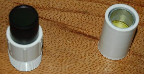
The optical assembly for the aurora monitor is done. I mounted the optical filter, PCX lens and longpass filter in PVC pipe fittings. Virtually all of the analog electronics (primarily in Samantha) have designs now. I will be able to compile a parts list and order soon.
November 7, 2013
This is the filter / lens assembly for the aurora moniitor. I am still working on a suitable preamplifier design for the SPM.
December 20, 2013
I have completed many of the science package designs. I have also expanded upon the concept for a photospectrometer. It will be a networkable device (as stated before). I plan to use a beamsplitter (to allow for sighting), light falls upon a diffraction grating, and is measured a rotating read head comprising of an SPM, a PCX lens and a stepper motor. A socket will be reserved on O'Neill for external smart devices. A socket for a dumb photometer (or any device with a 1 or 2 channel analog output) will be provided on Samantha. Below is a final list for sensors attached to Samantha:
RH Sensor- Dewpoint warning and sky quality calculations
Ring Thermocouple- Monitors ring temperature to compare with dew point
Air Temperature Sensor- Dewpoint calculations
Ambient Light Detector- Sky quality calculations
Infrared Sky Temperature Sensor- Sky quality calculations
Barometer- Sky quality calculations (optional, but reserved)
40 KHz receiver- Thunderstorm warning and radio astronomy
March 25, 2014
From the beginning, I had concerns on what the coldest temperature the Infrared Sky Temperature Sensor (IRSTS) could measure is. How efficient would the TEC remain at the potentially low temperatures the device would be exposed to? Since it works by sensing temperature differential, perhaps if I heat the base side, I could improve measurement of colder temperatures. In fact, one of the oldest ideas for the IRSTS was to keep the base at a fixed temperature (this was to make it an absolute temperature sensor and eliminate the need for cold junction compensation). But the idea was discarded because of power demand. The laser pointer, heater and the hydrogen line receiver are all power hogs; I just did not need another. But the doubts over a passive sensor remained, so I did some experiments with a 30 mmTEC (as a heater) to see what the minimum power requirements were. Over 200 mA, but at a very low voltage (1.5V). If I were to use a bucking converter, I could make the 6V supply think it was only providing 50-60 mA. Now that's better. I will have to build a demo to test using a heated sensor. But if it works, I will keep the cold junction compensator and add the heating TEC and bucking converter to the IRSTS design.