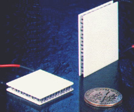
These wafer-like devices are made from two elements of of semiconductor (primarily bismuth telluride), heavily doped to create either an excess (n-type) or deficiency (p-type) of electrons. At the cold junction, energy (heat) is absorbed by electrons as they pass from a low energy level in the p-type semiconductor element to a higher energy level in the n-type semiconductor element. The DC power source provides the energy to move the electrons through the device. At the hot junction, energy is expelled to a heat sink as electrons move from a high energy level element (n-type) to a lower energy level element (p-type).
Temperature-Controlled Secondary
Due to the peculiarities of thermodynamics, the exposed mirror can cool down faster than the surrounding air- and below the dewpoint. That opens the possibility of the secondary mirror dewing up. The traditional solution is to use a heater (resistors, heat rope, etc.) of some sort. But now you're distorting the mirror. What I plan to try is using thermoelectric coolers to keep the mirror temperature above dewpoint, but only far enough to control dew formation. Sensors monitor the relative humidity, air temperature and mirror temperature, while a controller calculates whether the TEC should heat, cool, or stay off.
Temperature-Controlled Mirrors
Temperature-Controlled Mirrors
Cooler for primary mirror
I've been experimenting with ideas to speed up cooling down the primary mirror. Fans are the de facto solution, but there is room for improvement. I thought about using TECs to do the job, but the big question becomes how. Glue them to the bottom of the mirror? Even ignoring interference with the mirror cell, that whole approach is problematic. Each would need a sizeable heatsink, and with that, a potential problem with heated air from the TEC rising up around the mirror. Build them into the mirror cell? A lot of effort for a much more complicated design. What other options are there?
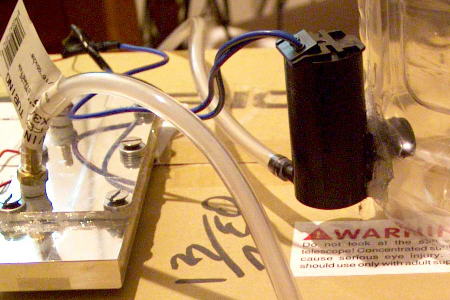
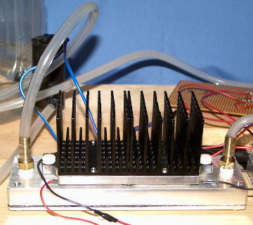
My designs all use a non-contact approach. Instead of cooling the mirror directly, a fan blows air cooled by TECs. In the first design, the TECs were cooled by icewater circulated by a windshield washer pump (Very much like the Cookbook Camera, for those of you familiar with it). I built a simple prototype (see below) with a heat exchanger milled out of aluminum on a CNC. I took an empty cider jug, cut a hole in the base, and glued the pump to it.
The heat exchanger and pump.
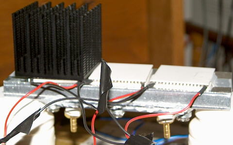
Top view of the heat exchanger, CPU heatsink and TECs.
I held off on building a full-scale version until I could test out several ideas with the prototype. One thing that I needed to test was the practicality of running full available power. Efficiency drops rapidly as current increases. Just look at the numbers. At 6 volt operation (two TECs wired in series), 9.6 watts per TEC moves a no-load 21 thermal watts. But at 12 volt operation (two TECs wired in parallel), 37.2 watts per TEC moves 32.5 no-load thermal watts. Put another way, to get a 55% increase of heat removal capacity requires a 288% increase in power. And most of that ends up as waste heat that has to be removed. To limit current, I can limit voltage. But, for the current needed for a full-scale cooler, variable-voltage control is not practical. So, with that, I have only two real options: A.) wire two in series for 6 volt operation or B.) wire two in parallel for 12 volt operation. And that's where another idea came in- use a relay wired to control two TECs, to alternate between 6 and 12 volt operation when needed.
My test begins by running the fan until the temperature would drop no more (to eliminate the fan as the source of the cooling). Then switch on the coolers, first in 6 volt mode, then 12 volt mode. When the first would cool no more, the next would be switched on.
The results of the final test are as follows:
Initial temperature: 72.05 degrees F
Fan cool-down: 72.00 degrees F
6 volt mode: 68.52 degrees F
12 volt mode: 68.17 degrees F
I went through two fuses to get my results. The conclusion is obvious, that there is no significant gain from running full 12 volt mode. Even TEC manufacturer's tech notes say that operating between 40 and 80% of the maximum power rating is best in terms of efficiency.
In the course of testing, I found that there was another problem to deal with- the pump was getting overly hot. It was never designed to run continuously. So, I lowered the voltage, and the motor stays at a reasonable temperature. At the lowered voltage, the pump managed to pump at the rate of 1/5 gallon per minute. But now I have two parallel-wired 10 ohm resistors that get hot enough to burn you! Plus, that heat is wasted power. Wasted battery power. So, I built a simple circuit to pulse-width modulate the power, which did not work as well as I'd hoped. But then I realized that what would work better was a DC-DC converter, which is readily available. After replacing the resistors with a Mean Well SKE15A12 DC-DC converter (which I got from Jameco) and a reverse-biased diode across the output (to protect the converter when the pump is turned on or off), my power efficiency increased from 38.4% to 80%. And the module never even gets warm! As a further bonus, since this is a regulated power supply, the pump voltage never varies (Even with such a large battery, the TECs load it down enough to pull the voltage down a half volt- enough to noticeably affect the pump. It also affects the fan, and I may have to use a similar approach there, as well.).
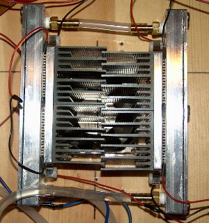
This prototype was successful enough to warrant making a full-scale version (see below). And unlike the prototype, these modules were much easier to work with. They didn't even need to be clamped in place during testing.
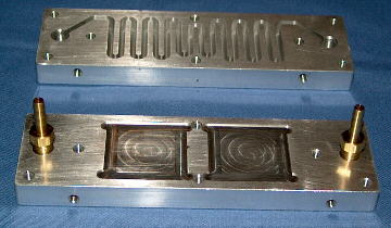
Top (showing serpentine channel for coolant) and bottom (showing seats for TEC chips) of heat exchanger.
Cold plate and back plate for heat exchanger.
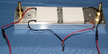
Heat exchanger with two TECs seated in place.
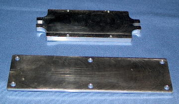
Two views of completed heat exchanger modules.
After mounting the heat exchanger to a board cut to fit the mirror cell, the assembly was tested, and it was quite an improvement over the prototype.
Initial temperature (fan running):79.88 degrees F
Cooler switched on (20 minutes):67.58 degrees F
Just like the design for my telescope has changed and matured, so has the design for the cooler. Before, the coolant was in a tank a distance away from the telescope. Later, it was to be in a small insulated tank mounted to the rocker, meaning quicker set-up and no hoses to trip over in the dark. And then an iceless cooler was conceived.
The iceless cooler was intended to eliminate the need for ice in the coolant. My experiments showed that I could never chill the gallon or so of coolant down that the previous design used to anywhere near the temperature of ice water using air-cooled TECs- the heat load is beyond what they could handle. But, by eliminating the tank and focus on cooling a much smaller quantity of coolant ( a pint or so), could make an iceless cooler practical. The result was a milled aluminum module- basically a super-sized version of the ones used to cool the main mirror, to be mounted on the back of the mirror box. A small reservoir for adding coolant and trapping air bubbles is included.
The prototype iceless cooler did work, but not very efficiently. Initially, I wasn't sure if the heatsink was inadequate or the device underpowered. So, I squeezed in another pair of TECs (from six to eight), and did get some improvement. But that increased the battery drain beyond what I considered acceptable. This test did verify that the heat load is too large for the TECs, which I clearly had miscalculated. So, Version 2 was designed. Two inches shorter, one tenth inch thinner and a half pound lighter. I calculated the ratio of TECs to module mass, and it tells the story. Both versions, interestingly enough, hold the same water load (close to 3.5 cubic inches) at any given time.
Version 13.125 (cubic inches of aluminum) to 1 (themoelectric cooler chip)
Version 22.2 (cubic inches of aluminum) to 1 (themoelectric cooler chip)
Version 2 was never constructed, and the whole idea of liquid cooling has largely been scrapped. It became too cumbersome and there were concerns with coolant leaking (water and optics don't go together).
No-Pump Mirror Cooler
The first mirror cooler designs use water circulating through heat exchangers under the primary mirror. I am currently working on a design that eliminates the pump and water. Since both the Stargate-2 and Stargate-3 are mostly made of aluminum, the mirror box is essentially one huge heat sink. Three assemblies consisting each of two TECs, a cold plate, small heat sinks, and two fans. The TECs cool the heat sinks, which the fan draws air through, blowing up to the primary mirror.
And for the record, I'm not the only one to come up with such an idea. I received an e-mail from an astronomer in Australia who had also built a Peltier-based mirror cooler. His design is very similar to my no-pump mirror cooler.
This page was last updated on: June 12, 2011
Introduction
For as long as I have been working on my telescope, I have been working on a system to control the mirror temperatures. With the secondary mirror, the objective is to keep dew from forming on the mirror. The secondary cage, aimed up into the sky, radiates heat and can actually cool below ambient air temperature. In the case of the primary mirror, as glass has a high thermal inertia, the objective is to speed up the cool-down time to the ambient air temperature. Temperature differentials cause distortion of the mirror, while microscopic in scale, are significant when compared to the wavelengths of light. A warmer than ambient mirror also causes a layer of air (and one with a slightly different index of refraction) just over the mirror to form.
Primary and secondary temperature sensors and secondary mirror temperature control elements.
Basics
The active central component of my designs for both the primary and secondary mirrors is the thermoelectric cooler (a.k.a. Peltier device), or TEC for short. Thermoelectric coolers should be called heat pumps, not 'coolers'. By reversing polarity, you can reverse the flow of heat. So, with these devices, you can closely and quicky change temperature (heaters only heat). And the hot side can get HOT. These devices have efficiencies in the 10-20% range, which means that most of that power going in becomes waste heat (an issue exploited with the secondary mirror control), which is why a heatsink is generally required.
Basic System
The basic idea is for a controller to monitor air temperature, relative humidity, and the temperature of the mirrors. If the primary mirror is significantly warmer than ambient temperature, the mirror cooler turns on. If the secondary mirror has cooled to near or below ambient temperature and is near the dew point, that mirror is heated.